제품정보
(메이커/스펙/옵션/액세서리/장비상태 등) |
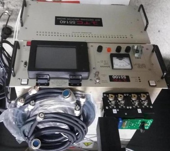
- ITC 55140 : SCR Switching Inductor Matrix .
The ITC55100STD is a single site 100A version of the industry standard series of ITC55100 testers. The ITC55100STD performs all the same tests as the ITC55100 system but has a single test port and a maximum drain current capability of 100A for improved price/performance in single DUT production testing applications.
Model ITC55100STD performs ruggedness testing of power MOSFETs and IGBTs. It also tests single and dual diodes, and forward and reverse bias of IGBTs when used with an optional ITC55-RSF Output Selector Box.
Military Specifications: ITC55100 Testers Conform to MIL-STD-750, Method 3470
Output Energy Limits: 1 millijoule to 0.0049 * (VDD)2
joules in 1 millijoule steps
(i.e., 50V = 12.375 joules, 100V = 49.5 joules, 150V = 111.375 joules)
Output Current x Time No Limit
(IT) Limit:
RTF Test Increment to Failure: Increments ID or L with programmable inductive load box attached
Current Sensor Scale Factor: 250 mV/Amp@ 0.1A to 40.0A, 25 mV/Amp @ 40.1A to 100A
Current Sensor Type: Hall Effect Sensor
Drain Current Range: 0.1 to 100 amperes in 0.1 ampere steps
Drain Voltage Range: Plus or Minus (N- or P- Channel) 10 -150 volts in 1 volt steps
Rated Drain-Source Avalanche 10 to 2500 volts in 1.0 volt steps
Voltage Range: (BVDSS)
Gate Pulse Voltage Range: Plus or minus (N- or P- channel) 2 - 20 volts in 1-volt steps
Leakage Test Forced Voltage = 2V to Programmed Drain Voltage (max.)
(Pre & Post Avalanche) I = 1.0 mA Imax = 8.0 mA
Solid State Power Switch: 100 amps
Gate Drive Resistance: 25Ω (50Ω per Kelvin leg)
Parameter Entry: Touch screen display on front panel. GPIB from host computer.
Any entry or calculated parameter that produces an out-of-range value indicates the parameter to be
changed and a Start Test cannot be initiated until the parameter error has been corrected.
Waveform Capture & Analysis: Waveforms can be captured and viewed on the LCD front panel display or via GPIB.
Outputs: One test output for testing N or P channel MOSFETs, IGBTs and single or dual diodes with optional RSF box.
|
 신품 · 중고계측기 전문회사