ME7848A
![]() > 메이커별제품 > Anritsu > 네트워크 분석기
> 메이커별제품 > Anritsu > 네트워크 분석기
VectorStar™ Opto-Electronic Network Analyzers ME7848A
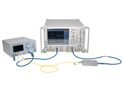
VectorStar ME7848A 광전자 네트워크 분석기 (ONA)는 850nm, 1310nm 및 1550nm 파장에서 작동하는 O/E, E/O 및 O/O 디바이스의 광학 측정에 대한 모듈식 접근 방식을 제공합니다. 두 가지 구성으로 사용 가능합니다. VectorStar ME7848A-100 시리즈에는 MN4765B O/E 교정 모듈이 포함되어 있으며 VectorStar ME7848A-200 시리즈에는 MN4775A E/O 컨버터가 추가되었습니다.
- • 빠르고 정확한 광전자 측정 : VectorStar ME7848A 200 시리즈 ONA를 사용하면 E/O 및 O/E 컴포넌트 및 하위 시스템의 오류 수정 전송 기능, 그룹 지연 및 반사 손실 측정이 가능합니다.
- • MN4765B O/E 교정 모듈 : O/E 교정 모듈은 온도에 따른 드리프트를 제거 할 수 있는 열적으로 안정화 된 포토 다이오드 참조 표준 검출기(detector)입니다. 포토 다이오드에 대한 정확한 바이어스(bias) 전압은 내부적으로 유지됩니다.
- • MN4775A E/O 컨버터 : E/O 컨버터에는 전자동 바이어스 컨트롤러와 조정 가능 또는 고정 파장 레이저 소스로 안정화 된 리튬 니오 베이트 (LiNbO3) 변조기(modulator)가 포함되어 있습니다. 뛰어난 컨버터 안정성으로 인해 광전자 DUT 검출기 및 수신기를 측정하는 동안 특성이 일관되게 유지됩니다.
- • NIST (National Institute of Standards and Technology) 파생 특성화 : O/E 교정 모듈의 크기 및 위상 특성화는 NIST가 특징으로 하는 주요 표준을 사용하여 획득되며 Anritsu Calibration Lab에서 유지됩니다.
System Components
| Performance |
|---|
| MS464xB Vector Network Analyzer with Option 51 (access loops; Option 61 or 62 may be chosen as options) |
| MN4765B-xxxx O/E Calibration Module |
| MN4775A-0040/0070/0071/0072/0110/0111 E/O Converter (-02XX systems only) |
| 1 m single mode patch cord (FC/PC-FC/APC) |
| Two 1 m RF cables |
| Fiber connector cleaning kit |
| Two semi-rigid cables to support the reversed coupler configuration |
제품 사양
| Basic Specifications1 | ||||
|---|---|---|---|---|
| ME7848A-0240 | ME7848A-0270 | ME7848A-0271 | ME7848A-0272 | |
| RF frequency rangea | 70 kHz-40 GHz | 70 kHz-70 GHz | 70 kHz-70 GHz | 70 kHz-70 GHz |
| RF connector type | K (2.92 mm) | V (1.85 mm) | V (1.85 mm) | V (1.85 mm) |
| Optical source input connector type (polarization-maintaining fiber recommended) | FC/PC | FC/PC | FC/PC | FC/PC |
| Optical output and modulated input connector type | FC/APC | FC/APC | FC/APC | FC/APC |
| Receiver wavelength range | 800 - 1700 nm | 1480 - 1620 nm | 1300 - 1330 nm | 1300 - 1330 nm and 1480 - 1620 nm |
| Receiver DC responsivity | > 0.2 A/W (850 ± 20 nm) |
> 0.7 A/W (1550 ± 20 nm) |
> 0.45 A/W (1319 ± 10nm) |
> 0.45 A/W (1319 ± 10nm) > 0.65 A/W (1550 nm ± 20 nm) |
| Maximum linear optical power to receiver (< 0.5 dB variance in frequency response shape) | 2 dBm | 6 dBm | 6 dBm | 6 dBm |
| Maximum safe optical power (average) to receiver | 6 dBm | 10 dBm | 10 dBm | 10 dBm |
| Optical return loss (modulation output and detection ports) | >24 dB | >24 dB | >24 dB | >24 dB |
| Average optical power uncertainty (transmit) | ± 0.5 dB | ± 0.5 dB | ± 0.5 dB | ± 0.5 dB |
| Optical modulation sensitivity (RF Vπ at 1 GHz, typical) | 2.3V pk-pk | 5.5V pk-pk | 5.5V pk-pk | 5.5V pk-pk |
| Transmit wavelength | 850 nm | 1527-1565 nm | 1310 nm | 1310 nm or 1527-1565 nm |
| Average output power range (typical) | -17 to -1b dBm | -15 to +5 dBm | -17 to +2 dBm | -20 to +4 dBm |
| Output power stability (over 4 hours and 3 °C temperature range) | ± 0.1 dB | ± 0.1 dB | ± 0.1 dB | ± 0.1 dB |
| Optical Modulation path loss (quadrature bias, typical) | 8 dB | 8 dB | 8 dB | 8 dB |
| 0.1 dB compression point of RF receiver (at port)a (characteristic) | > +5 dBm for 70 kHz to 300 kHz > +11 dBm above 300 kHz |
> +5 dBm for 70 kHz to 300 kHz > +11 dBm above 300 kHz |
> +5 dBm for 70 kHz to 300 kHz > +11 dBm above 300 kHz |
> +5 dBm for 70 kHz to 300 kHz > +11 dBm above 300 kHz |
| 0.1 dB compression point of RF receiver (at reversed port)a (characteristic) | > -15 dBm 70 kHz to 300 kHz > -10 dBm 300kHz to 2.5 GHz > -5 dBm above 2.5 GHz |
> -15 dBm 70 kHz to 300 kHz > -10 dBm 300kHz to 2.5 GHz > -5 dBm above 2.5 GHz |
> -15 dBm 70 kHz to 300 kHz > -10 dBm 300kHz to 2.5 GHz > -5 dBm above 2.5 GHz |
> -15 dBm 70 kHz to 300 kHz > -10 dBm 300kHz to 2.5 GHz > -5 dBm above 2.5 GHz |
| Modulation port return loss (raw)a | > 10 dB for < 20 GHz > 7.5 dB for 20 to 40 GHz | > 10 dB for < 20 GHz > 7.5 dB for 20 to < 50 GHz > 3 dB for 50 to 70 GHz |
> 10 dB for < 20 GHz > 7.5 dB for 20 to < 50 GHz > 3 dB for 50 to 70 GHz |
> 10 dB for < 20 GHz > 7.5 dB for 20 to < 50 GHz > 3 dB for 50 to 70 GHz |
| Detection port return loss (raw)a | > 10 dB for < 18 GHz > 3dB for 18 to 40 GHz | > 8 dB for < 50 GHz > 5 dB for 50 to 70 GHz | > 8 dB for < 50 GHz > 5 dB for 50 to 70 GHz | > 8 dB for < 50 GHz > 5 dB for 50 to 70 GHz |
| a. These line entries assume the presence of VNA option 070 (70 kHz lower frequency limit). Without option 070, the minimum frequency is 10 MHz. b. Recommended operation at -3 dBm and below for optimal modulator performance. 1. All system specifications are based on the modulator being biased in quadrature mode. |
||||
옵션 & 악세서리
| Standard Accessories | |
|---|---|
| Optical USB Mouse Power Cord 2000-1957-R : Accessory Kit, 40 GHz (-0x40 systems) 2000-1958-R : Accessory Kit, 70 GHz (-0x7x systems) 2000-2119-R : 1310 nm and 1550 nm Accessory kit, 110 GHz (-011x systems) |
|
| Accessory Kit Option | |
| 2000-1962-R | 40 GHz semi-rigid cable set |
| 2000-1964-R | 70 GHz semi-rigid cable set |
| 808-20-R | 850 nm, 1 m, patch cable |
| 808-21-R | 1310-1550 nm, 1 m patch cable |
| Automatic Calibrators (AutoCal) and Calibration Kit Option | |
| 36585V Series | Precision AutoCal module; K 70 kHz to 40 GHz, 2-port; V 70 kHz to 70 GHz, 2-port |
| 36585 Series | Precision AutoCal calibration kit |
| 3650A Series | SMA/3.5 mm calibration kit |
| 3652A Series | K (2.92 mm) calibration kit |
| 3654D Series | V (1.85 mm) calibration kit |
| 3657 Series | V (1.85 mm) multi-line calibration kit |